
Now, the worlds great 3d riddle (i guess), is how to move the blocks while keeping them attached:
I’ll try to get the riddle solved by tomorrow… It might be the last riddle…
Find the center of both cubes and make the points rotate around that one. That’s how I’d try it.
You’d pretty much have to make a new “track” on demand. You might have to find a way to unite 2 cubes and… well I can’t help you much from there.
WicKad is slowly taking shape ![]()
I know what u mean, I’ll probably just need to stretch out the track and combine the cubes. However, the reason I didn’t do this idea is because not all cubes are going to be combined really, some need to be separate apart. The two cubes are going to move not as if they’re connected, but as if they’re just plain blocks that are touching. So, really I’ll make the blocks move based on a viewpoint. The closer they are to ur view-point, the less they’re going to move and rotate. It’s like that one equation u made that made me think stronger of this being possible:
this.x+=(this.x-viewPoint.x)/2;
this.y+=(this.y-viewPoint.y)/2;
(btw, I’ll definitely need to use ur equation, if u don’t mind, cause it’s just brilliant. I’ll give u credit too)
Off topic, but what is WicKad?
cad is a tool that makes 3d stuff. we’re kinda making 3d stuff… so that’s why i said that. although cad lets you 3d print your creation, so it’s not quite cad.
So you want the blocks to collide? Or at least stop rotating when it hits something?
EDIT:
I think I might’ve found the solution to that 3d riddle, but I’ll have to start over almost everything
Apparently, if what I have planned on my mind is exactly what the results are going to be, it’s going to be the last part of the whole 3d puzzle! If u see, the puzzle is starting to connect! The oval track, awc’s equation, the viewpoint, raycasting, and cad!
Here's how
Raycasting is based on a view-point. I’ll have the same view-point and the raycasting lines need to be curved like an oval curve. The closer it is to the middle, the less curvy. This looks like the cad orbit tool. Here’s how it looks:
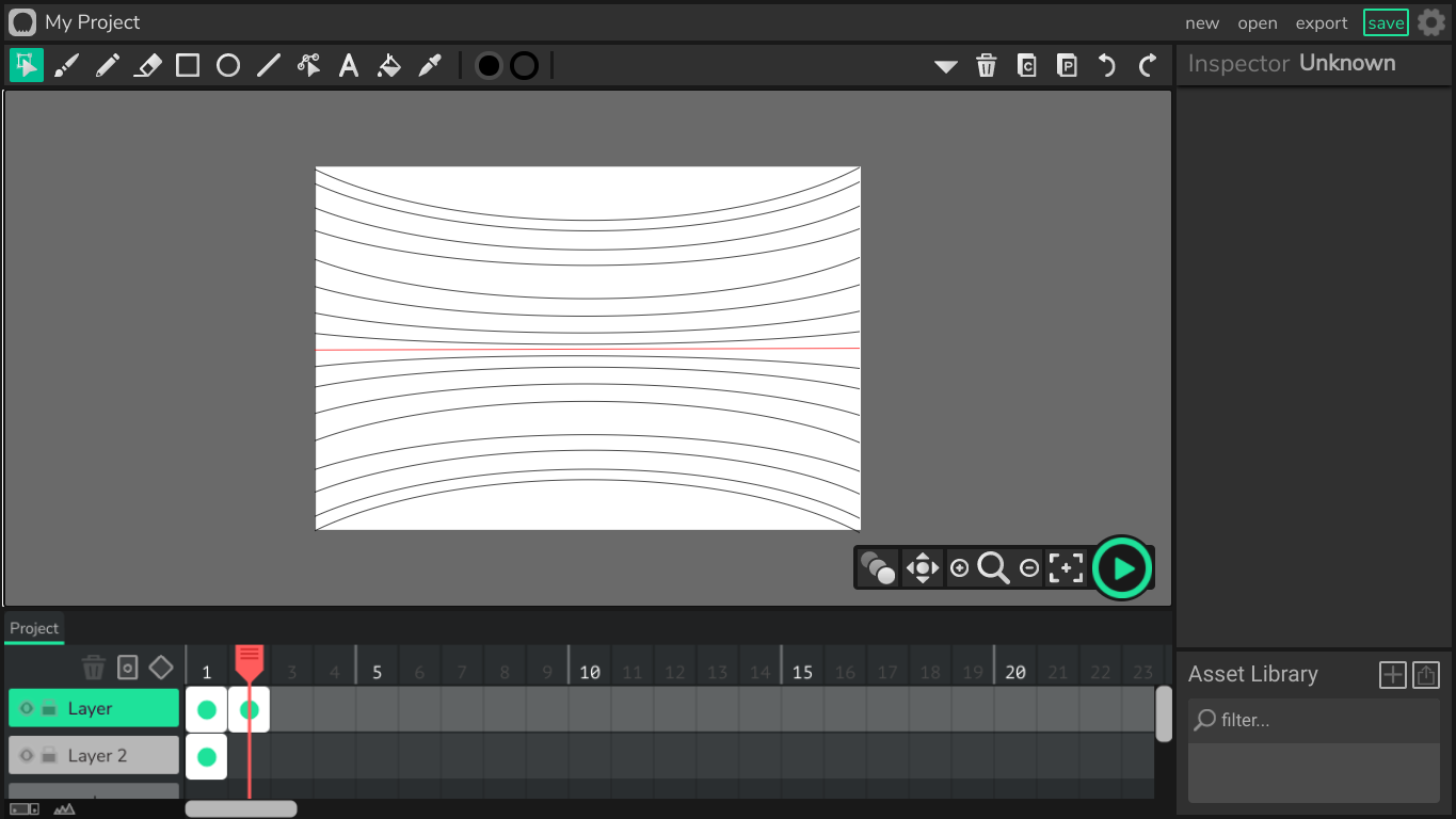
Now, these lines also have a pattern. So, since a pattern exists, I won’t need to literally have these lines in the project. The closer the line is to the middle, the greater the x, the least the y, and the farther it is, the farther the y goes and the least the x goes. That’s where awc’s equation comes in. Its pattern is close to this one, but not quite the same. I’ll need to add on to it to fit my needs for this project. Now, I’ll just have to hope for success, I’ll still keep u guys updated if anything happens.
Also, I do know what cad is, just got confused when u combined it with Wick. It was really the first and only 3d designing website that I had used, and it’s just great!
3D graphics is always done by taking 3D points and projecting them onto a 2D plane, kind of like what you are doing… I think. How do you create shapes in Wick? Can you even do that?
I got kinda confused by you talking about my “equation” but I’m guessing you just took my english and turned it into math/code.
That looks amazing by the way :D
1 Like
It seems that the edges of the cube/prism either extend or shorten based on whether it’s touching it’s target point. Do you think you’d be able to calculate the distance instead, so it won’t be too short or too long when it’s moving and the perspective changes?
I see what u mean. It’ll really just depends on the distance between the dots. I once had an equation for this, but now I really don’t have that file anymore (I saved it as a project, and forgot to rename it, and sadly, I have 100’s of unnamed project to look through. Wick really needs a “save project as” button).
EDIT:
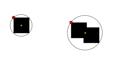
I just tried to remake it, it’s more complicated than it seems. Take a look:
It rotates somehow around an imaginary point that I marked as a red dot. That red dot is a simple dot, it isn’t a clip. The line rotates towards the mouse and becomes long enough to exactly touch the mouse (that’s only if it was a bit more on the left).
1 Like
Quick update:
I found it! I had to make a new equation, here’s how it looks:
It rotates towards the mouse, as well as stretches out towards it, although it’s kinda off from the mouse by a tiny tiny bit!
try it.html (2.1 MB)
It was as simple as these two lines:
this.height=(this.y-mouseY)
this.width=1.535+(mouseX-this.x);
1 Like
I just have to say, this is one of the most interesting threads I’ve ever seen on the forum. Would love to see if someone could create an interactive experience or game using these techniques!
9 Likes
oh that’s how you made the lines stretch, i thought you somehow figured out to manipulate the points in the shape using some undocumented property
1 Like
I think I could help you with this. I made a way to make the lines extend to a point by setting only its width and making the clip rotate towards the desired point. I made it this way because when I drew the line I set the line height to 0 so it wouldn’t let me change the size Y the line would just disappear.
This looks very accurate. However, the farther away the point is the more the line length will be off.
line-demo.html (2.0 MB)
Here is the code. This is what I put in the default script
this.originX = 445;
this.originY = 252.5;

this.pointTowards = function(x, y) {
    //get xy differences
    var dx = (x - this.originX);
    var dy = (y - this.originY);

    //normalize dx and dy (so they have a distance of one)
    var dist = Math.sqrt(dx * dx + dy * dy); //calculate distance

    var unitX = dx / (dist || 1); //if dist == 0 (a.k.a. false) then use 1 instead
    var unitY = dy / (dist || 1);

    this.width = dist;
    this.x = unitX * (this.width / 2) + this.originX;
    this.y = unitY * (this.width / 2) + this.originY;

    var rot = Math.atan2(dy, dx); //calculate rotation (in radians)
    this.rotation = rot / Math.PI * 180; //convert radians to degrees
};
EDIT: i made some changes to the code
EDIT: i noted the first edit
4 Likes
Wow @pumpkinhead, ur code looks well organized and is definitely more accurate.
I’m kinda rushing through the project, so this’ll be pretty helpful, thanks for the help :D
1 Like
Well, the project almost stopped working when I was near finishing the whole 3d project, so I had to try to make the project work faster. This is literally how slow it was:
It would freeze for 10 seconds then go on, so I went back to the old two lines of code for the line movement and had to delete some other stuff. Here’s the project:
3d 5 cubes.wick (140.5 KB)
3d 3 cubes.wick (85.2 KB)
3d 3 cubes connected.wick (91.3 KB)
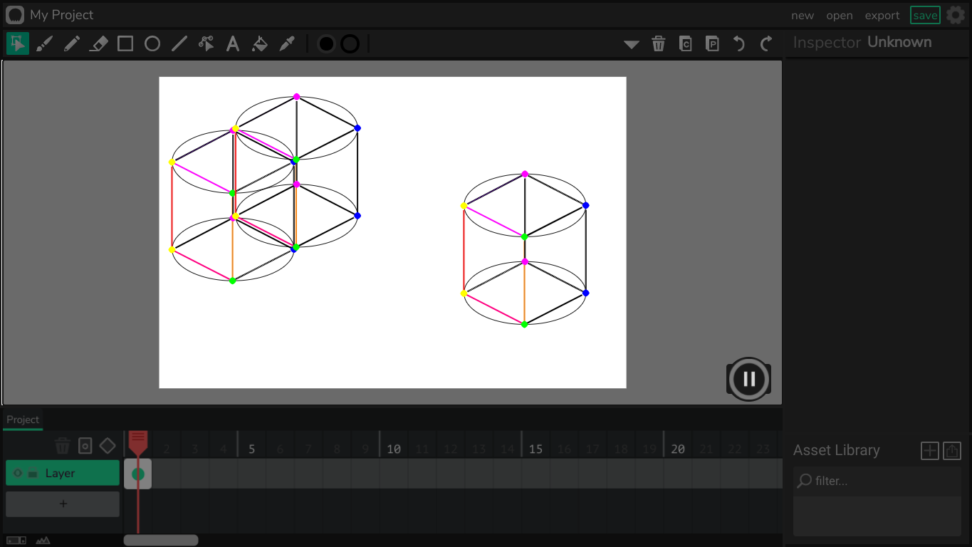
The last update that I did was find an accurate movement orbit that I had to clone for every cube, and the rotation of the orbit was measured to be the same as the rotation track for the cubes. The cube would face the middle with the same side, always. The location of the cubes has to be coded in based on the orbit, so if you’ll want to use this project as a 3d template, you’ll have to do some math. Thanks to those people who helped: @BaronAWC , @pumpkinhead , and me.
2 Likes
I gotta say, your attempt at 3D was very successful.
1 Like
I found another way to make the lines work. I am very confident that this won’t be slow. It is also 100% accurate and will work with any type of line thickness.
For it to work, you need to make a clip. Then make a single line using the line tool inside the clip. Then put this function into the clip:
this.setPoints = function(x0, y0, x1, y1) {
    //get line
    var frame = this.timeline.activeFrame;
    var lineObj = frame._children[0];

    //set points
    var segments = lineObj.view.item.curves[0];

    var dx = x1 - x0;
    var dy = y1 - y0;

    segments.point1.x = 0;
    segments.point1.y = 0;

    segments.point2.x = dx;
    segments.point2.y = dy;

    this.x = x0;
    this.y = y0;
};
Using some undocumented properties it will adjust the ends of the lines to the positions specified in the parameters.
2 Likes